23.06.2026
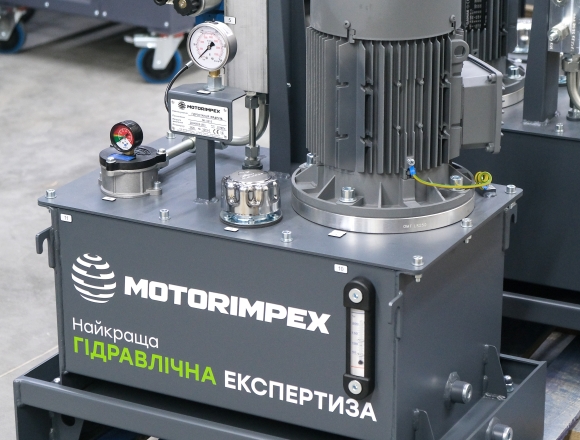
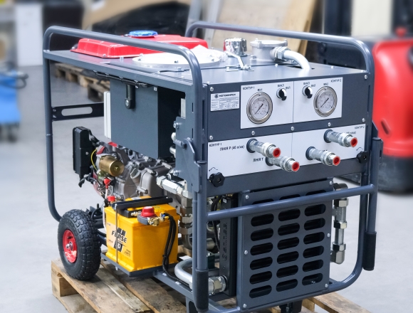
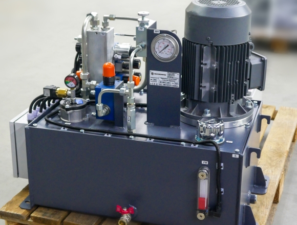
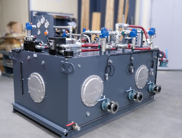
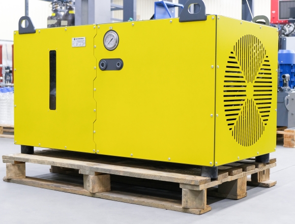
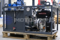
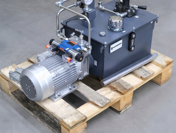
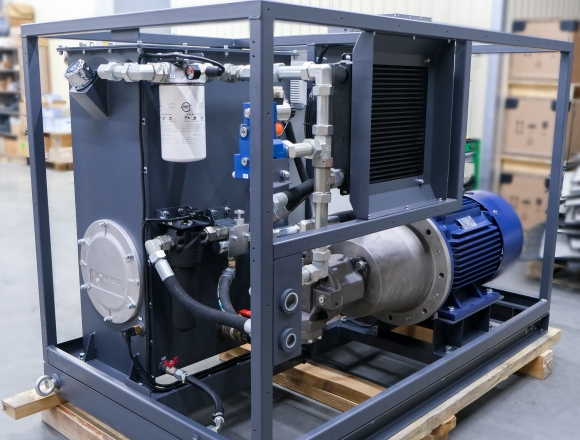
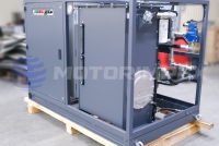
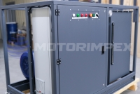
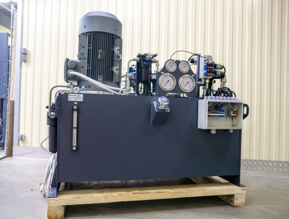
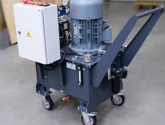
Let’s take a closer look at KRAPLYA — a new compact hydraulic power unit
Detail

Trading company "Motorimpex" is the largest supplier of flow dividers for high-pressure hydraulic systems in Ukraine. We represent the nomenclature from exclusive brands.
A wide range of product models is constantly in stock. All products from the technical catalogs are available for order.

G3/8
maximum working pressure: 350 bar
maximum flow rate: 40 l/min
flow division error: ± 3%

maximum working pressure: 250 bar
maximum working capacity: 33 cm3/rev
flow division error: ± 2%
aluminum housing

maximum working pressure: 310 bar
maximum working capacity: 125 cm3/rev
flow division error: ± 2%
cast iron housing

maximum working pressure: 210 bar
maximum working capacity: 2.3 cm3/rev
flow division error: ± 3%

maximum working pressure: 220 bar
maximum working capacity: 9.8 cm3/rev
flow division error: ± 3%

maximum working pressure: 210 bar
maximum working capacity: 40 cm3/rev
flow division error: ± 3%

maximum working pressure: 300 bar
maximum working capacity: 90 cm3/rev
flow division error: ± 3%

G3/8, G1/2, G3/4
maximum working pressure: 250 bar
maximum flow rate: 150 l/min
flow division error: ± 3%

G3/8, G1/2
maximum working pressure: 250 bar
maximum flow rate: 80 l/min
flow division error: ± 3%

maximum working pressure: 300 bar
maximum flow rate: 500 l/min
maximum working capacity: 2127 cm3/rev

maximum working pressure: 250 bar
maximum working capacity: 9.8 cm3/rev
flow division error: ± 1.6%

G3/8–G1
maximum working pressure: 210 bar
maximum flow rate: 150 l/min
flow division error: ± 5%
")
G3/8–G1 1/4
maximum working pressure: 350 bar
maximum flow rate: 250 l/min
flow division error: ± 5%

7/8–14 UNF
maximum working pressure: 350 bar
maximum flow rate: 45 l/min
flow division error: ± 2%

M27x2
maximum working pressure: 350 bar
maximum flow rate: 60 l/min
flow division error: ± 2%

1 5/16–12 UNF
maximum working pressure: 350 bar
maximum flow rate: 150 l/min
flow division error: ± 2.5 %

maximum working pressure: 210 bar
maximum working volume: 2.3 cm3/rev
flow division error: ± 3%

maximum working pressure: 210 bar
maximum working capacity: 2.3 cm3/rev
flow division error: ± 3%

maximum working pressure: 210 bar
maximum working capacity: 2.3 cm3/rev
flow division error: ± 3%

maximum working pressure: 210 bar
maximum working capacity: 2.3 cm3/rev
flow division error: ± 3%

maximum working pressure: 210 bar
maximum working capacity: 2.3 cm3/rev
flow division error: ± 3%

maximum working pressure: 220 bar
maximum working capacity: 9.8 cm3/rev
flow division error: ± 3%

maximum working pressure: 220 bar
maximum working capacity: 9.8 cm3/rev
flow division error: ± 3%

maximum working pressure: 220 bar
maximum working capacity: 9.8 cm3/rev
flow division error: ± 3%

maximum working pressure: 220 bar
maximum working capacity: 9.8 cm3/rev
flow division error: ± 3%

maximum working pressure: 220 bar
maximum working capacity: 9.8 cm3/rev
flow division error: ± 3%

maximum working pressure: 210 bar
maximum working capacity: 40 cm3/rev
flow division error: ± 3%

G3/8, G1/2
maximum working pressure: 210 bar
maximum flow rate: 38 l/min

G3/4, G1, G1 1/4
maximum working pressure: 210 bar
maximum flow rate: 167 l/min

maximum working pressure: 250 bar
maximum working capacity: 26 cm3/rev

maximum working pressure: 250 bar
maximum working capacity: 26 cm3/rev

G3/8–G1/2, G1/2–G3/4
maximum working pressure: 280 bar
maximum working capacity: 30 cm3/rev

M18x1.5, M22x1.5, M27x2, M33x2
G3/8–G1
maximum working pressure: 315 bar
maximum flow rate: 250 l/min
flow division error: ± 3%

G1/2, G3/4, G1
maximum working pressure: 420 bar
maximum flow rate: 250 l/min
flow division error: ± 3%

G3/8
maximum working pressure: 315 bar
maximum flow rate: 50 l/min
flow division error: ± 1.5 %

maximum working pressure: 250 bar
maximum flow rate: 2000 l/min
maximum working capacity: 250 cm3/rev
flow division error: ± 2%

maximum working pressure: 280 bar
maximum flow rate: 490 l/min
maximum working capacity: 3479 cm3/rev
flow division error: ± 0.5%

G3/8, G1/2
maximum working pressure: 300 bar
maximum flow rate: 80 l/min
flow division error: ± 2 %
Hydraulic flow divider – this is a device that allows you to distribute the flow of the working fluid evenly over two or more channels, regardless of what input load is applied to the hydraulic actuator.
Flow dividers are used in hydraulic systems where there is a need to synchronize the movement of several hydraulic motors and hydraulic cylinders. Thanks to this, the flow is precisely distributed in hydrostatic support systems and others.
According to the design features, the oil flow divider is divided into types:
If you need to buy a flow divider for hydraulic – welcome to our catalog! We offer the most reasonable prices in Ukraine and guarantee a high level of service.

tank capacity: 15 / 30 l
flow rate: 4.5 / 9 l/min
engine power: 1.5 / 2.2 kW
relief valve: 150 / 120 bar

pulling force: 6.8 t
flow rate: 60 l/min
working pressure: 155 bar
rope: 25 m x Ø 12 mm

pulling force: 4.5 t
motor displacement: 50 cm3/rev
flow rate: 5 - 45 l/min
rope: 25 m x Ø 10 mm

for testing and servicing hydraulic cylinders, with pressure control and idle speed control

maximum working pressure: 400 bar
maximum displacement of section: 75.1 cm3/rev

DN 6, 10
maximum working pressure: 315 bar
maximum flow rate: 180 l/min

capacity: 0.075–4 l
maximum working pressure: 350 bar

G3/8
maximum working pressure: 350 bar
 series")
G1/8, М5х0,8, G1/4, G3/8, G1/2
scheme: 5/2, 5/3
max. number of cycles per sec.: 5
response time: 0,05 sec

G1/8 – G1
maximum flow rate: 5200 l/min