23.06.2026
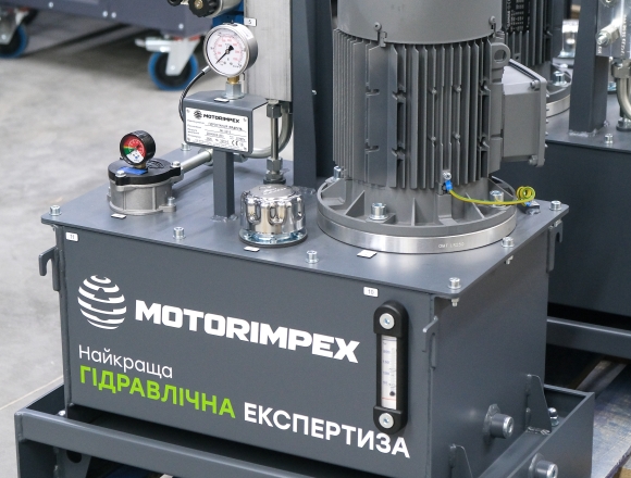
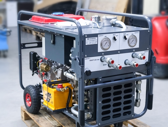
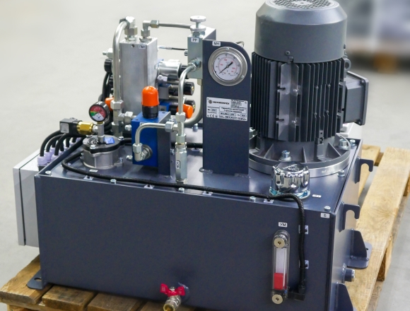
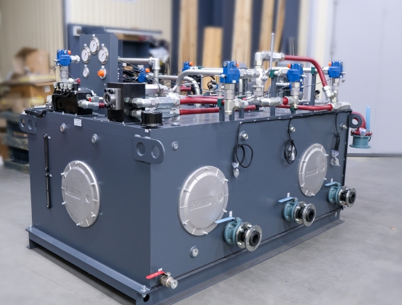
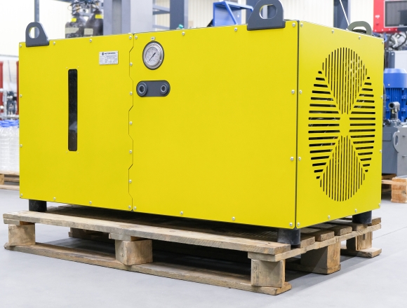
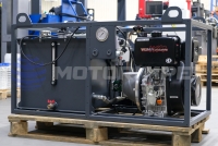
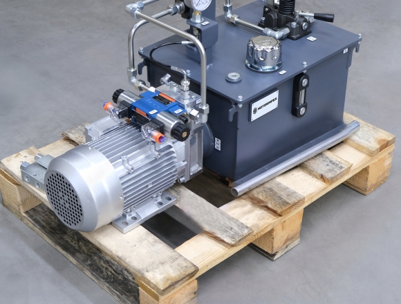
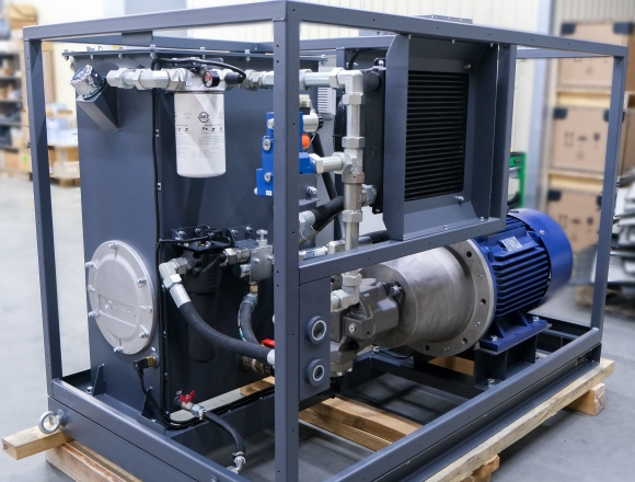
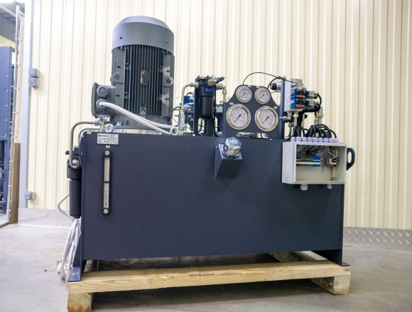
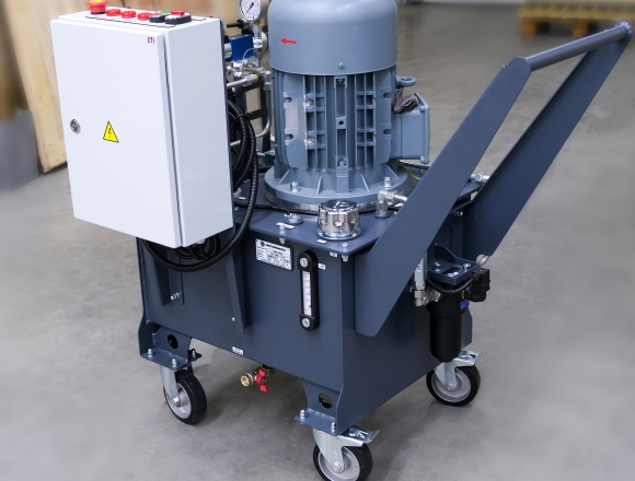
Let’s take a closer look at KRAPLYA — a new compact hydraulic power unit
Detail

We are a leader in the supply of hydraulic distributors in Ukraine. We have the largest hydraulic warehouses in the country, and a large part of the product brands is represented exclusively by us.
A wide range of product models is always in stock to quickly meet customer needs. All products listed in the technical catalogs are available for order.

DN 6
maximum working pressure: 350 bar
maximum flow rate: 25 l/min

DN 6, 10
maximum working pressure: 350 bar
maximum flow rate: 120 l/min

DN 6
maximum working pressure: 420 bar
maximum flow rate: 25 l/min

up to 6 spool valves
maximum working pressure: 300 bar
maximum flow rate: 80 l/min
with manual override

up to 12 sections
maximum working pressure: 315 bar
maximum flow rate: 80 l/min

7/8-14 UNF
2-way
maximum working pressure: 420 bar
maximum flow rate: 120 l/min

7/8-14 UNF
2-way
maximum working pressure: 350 bar
maximum flow rate: 80 l/min

M18x1.5
2-way
maximum working pressure: 350 bar
maximum flow rate: 40 l/min

G3/4
maximum working pressure: 350 bar
maximum flow rate: 140 l/min

G1
maximum working pressure: 350 bar
maximum flow rate: 250 l/min

DN 6
maximum working pressure: 350 bar
maximum flow rate: 80 l/min

DN 10
maximum working pressure: 350 bar
maximum flow rate: 160 l/min

DN 16
maximum working pressure: 350 bar
maximum flow rate: 240 l/min

up to 7 spool valves
maximum working pressure: 300 bar
maximum flow rate: 40 l/min

up to 6 spool valves
maximum working pressure: 300 bar
maximum flow rate: 80 l/min

up to 4 spool valves
maximum working pressure: 300 bar
maximum flow rate: 120 l/min

up to 7 spool valves
maximum working pressure: 250 bar
maximum flow rate: 50 l/min

010 – threaded on both sides, 054 – ball with KIT, 059 – ball without KIT, 029 – fork without KIT, 061 – fork with KIT
length: 1–3 m

G3/8"
up to 8 sections
maximum working pressure: 315 bar
maximum flow rate: 40 l/min

DN 6
maximum working pressure: 350 bar
maximum flow rate: 80 l/min

DN 6, 10
maximum working pressure: 350 bar
maximum flow rate: 120 l/min

DN 10
maximum working pressure: 350 bar
maximum flow rate: 130 l/min

DN 6, 10
maximum working pressure: 350 bar
maximum flow rate: 100 l/min

DN 6
maximum working pressure: 350 bar
maximum flow rate: 30 l/min

DN 6
maximum working pressure: 315 bar
maximum flow rate: 80 l/min

DN 10
maximum working pressure: 315 bar
maximum flow rate: 120 l/min

DN 16, 25, 32
maximum working pressure: 350 bar
maximum flow rate: 1100 l/min

G3/8, G1/2, M18x1.5
up to 6 sections
maximum working pressure: 250 bar
maximum flow rate: 50 l/min

up to 6 spool valves
maximum working pressure: 300 bar
maximum flow rate: 80 l/min

up to 8 sections
maximum working pressure: 300 bar
maximum flow rate: 70 l/min

DN 6
maximum working pressure: 315 bar
maximum flow rate: 80 l/min

DN 10
maximum working pressure: 350 bar
maximum flow rate: 160 l/min

DN 6
maximum working pressure: 350 bar
maximum flow rate: 60 l/min

up to 6 spool valves
maximum working pressure: 300 bar
maximum flow rate: 80 l/min
with manual override

up to 12 sections
maximum working pressure: 315 bar
maximum flow rate: 100 l/min

up to 12 sections
maximum working pressure: 315 bar
maximum flow rate: 150 l/min

DN 10
maximum working pressure: 350 bar
maximum flow rate: 150 l/min

DN 6

DN 6, 10, 16, 22
maximum working pressure: 350 bar
maximum flow rate: 1000 l/min

DN 10, 16, 22, 32
maximum working pressure: 350 bar
maximum flow rate: 1000 l/min

3/4–16 UNF
2-way
maximum working pressure: 300 bar
maximum flow rate: 40 l/min

3/4–16 UNF
2-way
maximum working pressure: 300 bar
maximum flow rate: 40 l/min

G3/4
2-way
maximum working pressure: 300 bar
maximum flow rate: 80 l/min

G1
2-way
maximum working pressure: 300 bar
maximum flow rate: 150 l/min

3/4–16 UNF
2-way
maximum working pressure: 210 bar
maximum flow rate: 25 l/min

1–1/16 UNF
2-way, double lock
maximum working pressure: 250 bar
maximum flow rate: 130 l/min

up to 8 sections
maximum working pressure: 350 bar
maximum flow rate: 95 l/min

G3/8, G1/2
2-way
maximum working pressure: 207 bar
maximum flow rate: 22 l/min
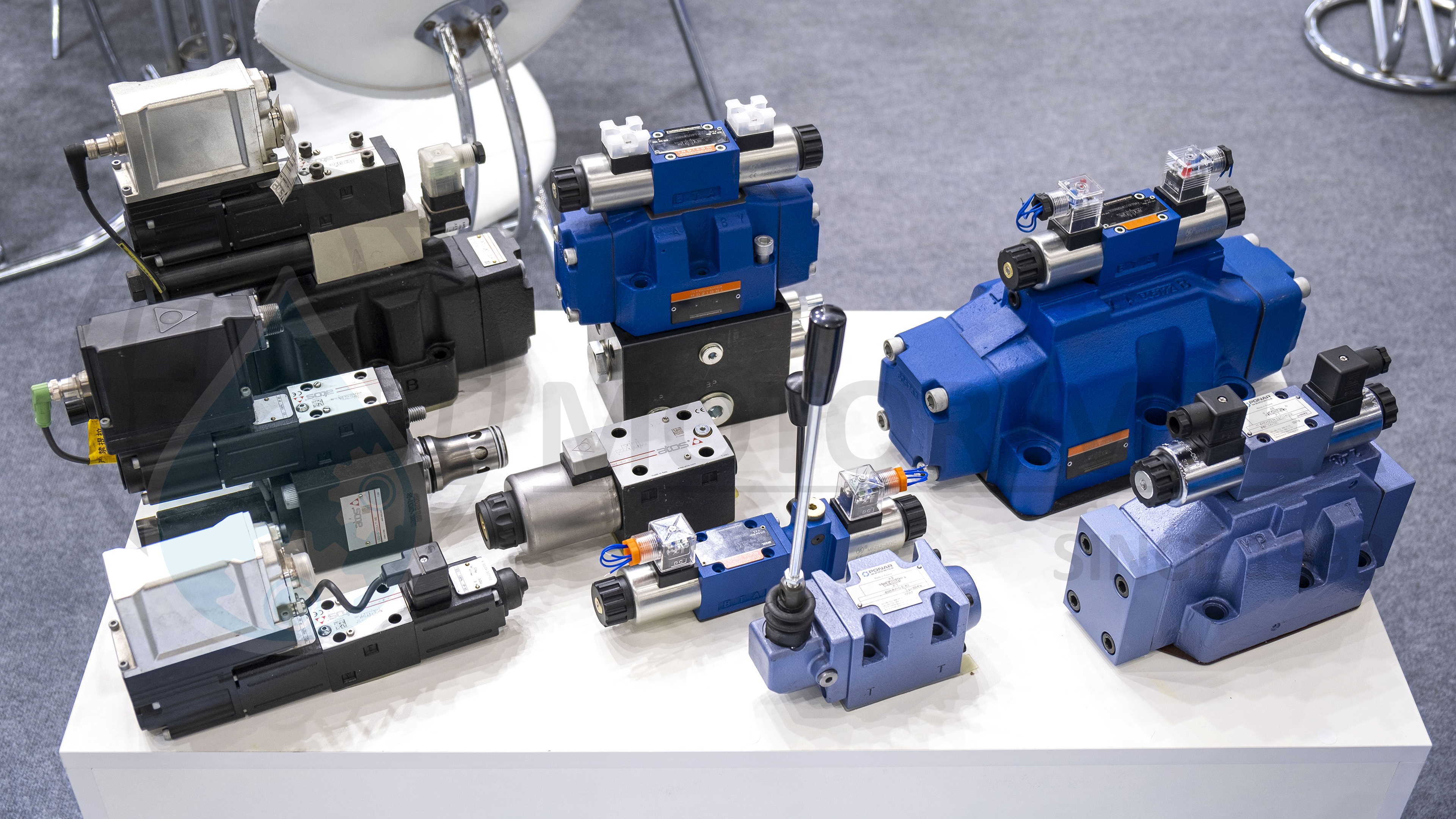
The directional control valves directs the flow of working fluid into various chambers of the actuators within the hydraulic system. The pressurized oil flow moves the working components of equipment and special machinery, such as machines, presses, manipulators, and other similar devices.
The primary component in most directional control valves is the control element, which in 95% of cases is a spool valve. The advantages of spool-type directional control valves include reliability, durability, cost-effectiveness, ease of manufacturing, and interchangeability. Directional control valves with seat-type control elements (such as balls, cones, or discs) are less common due to their lower flow capacity and higher cost.ть.
The main task of a directional control valves is to correctly direct the fluid flow to all necessary parts, elements, or components within the entire hydraulic system.
Directional control valve transfers hydraulic power from the source (pumps), which pressurizes the hydraulic fluid flow to the actuator (hydraulic cylinder, hydraulic motor).
Based on the received data (proportional or discrete electrical signal), the directional control valve determines how to distribute the flow between hydraulic cylinders, motors, and other devices.
Directional control valves are classified by the type of control applied to the shut-off and control element. Ranked by decreasing frequency of use in hydraulic drives:
— Manual;
— Electromagnetic;
— Electro-hydraulic;
— Electromagnetic with manual override;
— Hydraulic;
— Mechanical;
— Pneumatic.
Depending on the tasks the hydraulic system needs to solve, combined types of directional control valve control are often used.
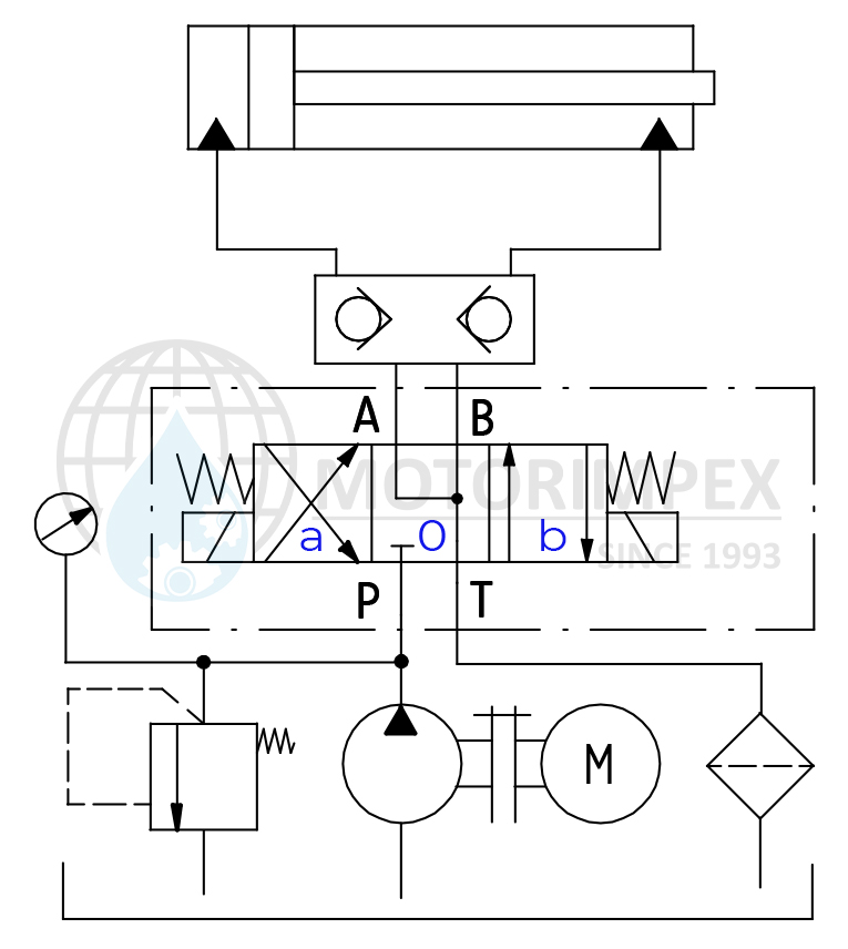
The directional control valve functions based on the configuration of the edges on the spool valve body, which, in the appropriate working positions, connect and separate the channels A, B, P, and T. The distribution scheme is selected according to the required operating modes of the hydraulic system..
When held in a neutral position by return springs, the spool valve either unloads the system or keeps the flow of working fluid closed. When acted upon by one of the control types, the spool moves to a working position and connects the corresponding channels, through which the fluid movement activates the actuators in the required direction. When the control influence on the shut-off and control element ceases, it returns to its original position.
For additional safety, directional control valves are often equipped with limit switches to monitor the spool valve position.
In the provided diagram, in position "0" of the electromagnetic control, the fluid flow from the hydraulic pump to the cylinder is blocked. In position "b", fluid under pressure from channel P flows through channel A into the piston chamber of the hydraulic cylinder. The rod extends, and at the same time, oil from the rod chamber is drained from channel B through channel T into the hydraulic tank. When the spool of the directional control valve is switched to position «a» the rod chamber is filled, and the working fluid from the piston chamber is drained — thus retracting the cylinder rod.
The main types of connection are face (plate) and threaded.
Face-mounted directional control valves have a standardized nominal diameter (ND) and port arrangement. The port side of the directional control valve body is tightly aligned with the corresponding port configuration on the side of the mounting plate or modular valve. The mated surfaces of the plates are tightly bolted together, most commonly found in machine tool hydraulic drives.
Monoblock and sectional directional control valves with threaded ports are connected by high-pressure hoses or pipes, most commonly used on tractors, graders, manipulators, and similar special machiner.
Cartridge mounting refers to normally-open and normally-closed directional control valves, which are screwed into mounting plates via the threaded part of their body.
Depending on the number of actuators (operations), the system must have a corresponding number of channels. For this purpose, face-mounted directional control valves are assembled in sets on a mounting plate, while threaded directional control valves are either manufactured with multiple spools in a single body or assembled from sections. Each spool can have an individual configuration in such assemblies.
A directional control valve is a component within a hydraulic system that controls the direction of fluid flow. The directional control valve receives hydraulic fluid and directs it to the necessary actuators (such as pistons, motors, and mechanisms). This component can be controlled by either an operator or an electronic control unit.
Different types of directional control valves and their descriptions are listed in the table:
|
Type of Directional Control Valve |
Description |
|
Monoblock |
All necessary components are housed within a single body |
|
Multiblock |
Comprised of multiple blocks that work together |
|
Two-position |
Used to control two states of a system, such as forward/backward movement |
|
Three-position |
Used to control three states of a system, such as forward/backward movement, and stopping at a desired position |
|
Proportional |
Provides maximum precision in movements |
A smart choice is to purchase a directional control valve from MOTORIMPEX, as the company provides licensed equipment and has extensive experience in installation, operation, and maintenance, whether as a standalone unit or integrated into complete hydraulic systems.

tank capacity: 15 / 30 l
flow rate: 4.5 / 9 l/min
engine power: 1.5 / 2.2 kW
relief valve: 150 / 120 bar

pulling force: 6.8 t
flow rate: 60 l/min
working pressure: 155 bar
rope: 25 m x Ø 12 mm

pulling force: 4.5 t
motor displacement: 50 cm3/rev
flow rate: 5 - 45 l/min
rope: 25 m x Ø 10 mm

for testing and servicing hydraulic cylinders, with pressure control and idle speed control

maximum working pressure: 400 bar
maximum displacement of section: 75.1 cm3/rev

DN 6, 10
maximum working pressure: 315 bar
maximum flow rate: 180 l/min

capacity: 0.075–4 l
maximum working pressure: 350 bar

G3/8
maximum working pressure: 350 bar
 series")
G1/8, М5х0,8, G1/4, G3/8, G1/2
scheme: 5/2, 5/3
max. number of cycles per sec.: 5
response time: 0,05 sec

G1/8 – G1
maximum flow rate: 5200 l/min