23.06.2026
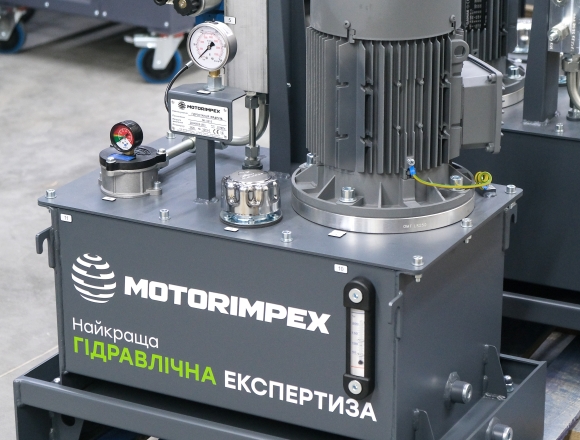
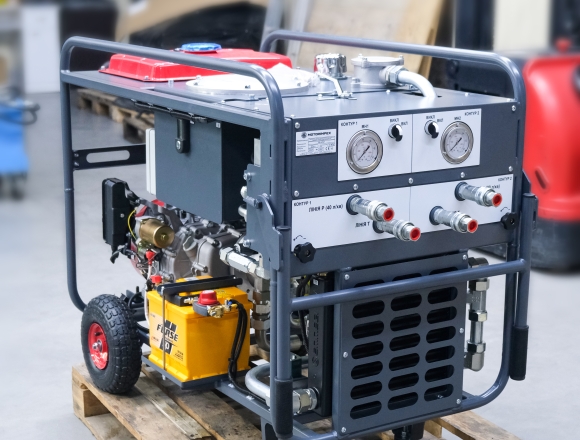
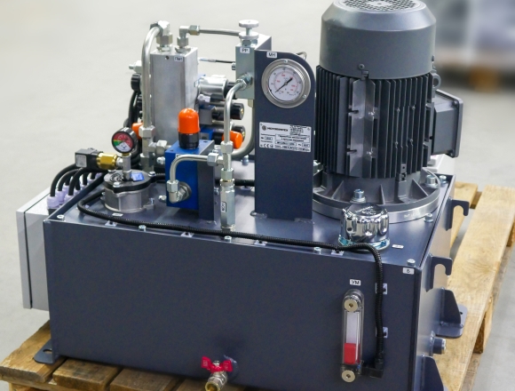
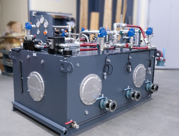
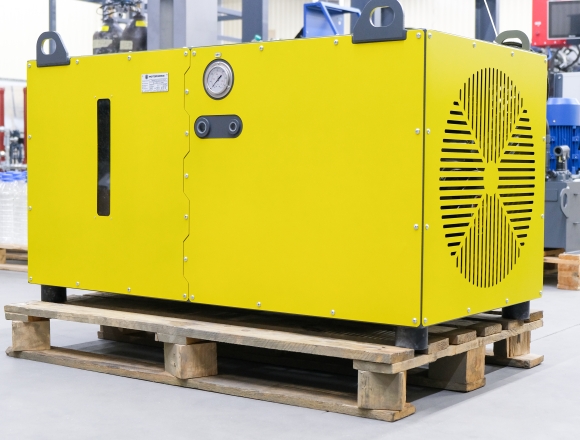
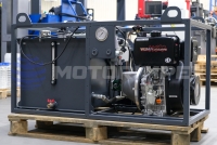
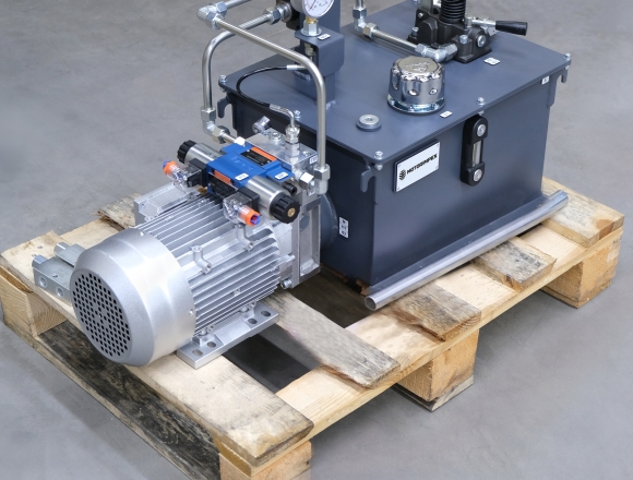
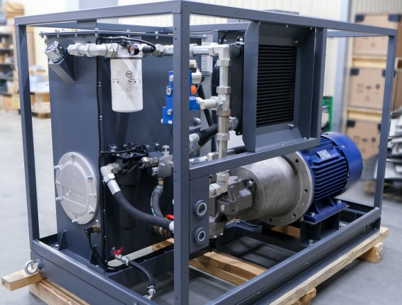
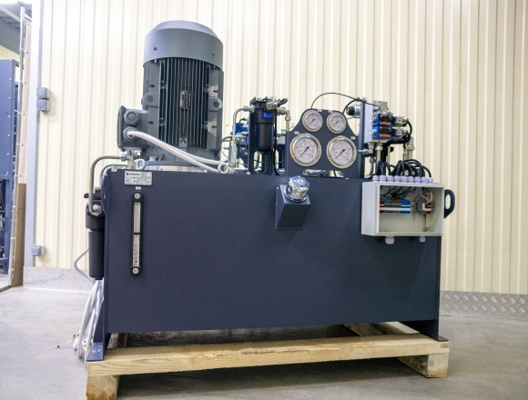
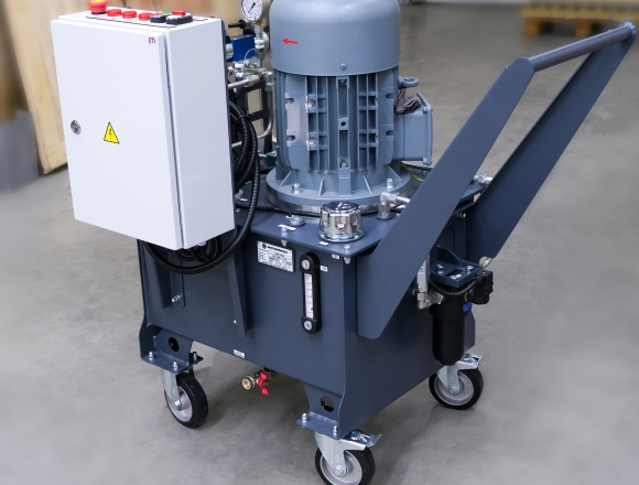
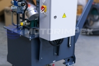
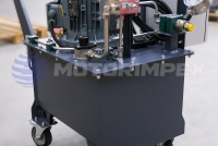
Let’s take a closer look at KRAPLYA — a new compact hydraulic power unit
Detail

We also supply coils and solenoids for hydraulic valves. Most product manufacturers are represented exclusively.
A wide selection of models is always in stock for quick supply. All nomenclature listed in the technical catalogs is available for order.

12, 24 VDC
110, 220 VAC
Ø int 23 mm

12, 24 VDC
110, 220 VAC
Ø int 31,6 mm

12, 24 VDC
24, 110, 220 VAC
Ø ext 13, 14, 16 mm

12, 24, 96, 110, 206 VDC
7/8–14 UNF

12, 21, 24, 42, 48, 60, 96, 110, 125, 206, 220 VDC
Ø ext 23 mm

12, 24, 42, 48, 60, 96, 110, 125, 206, 220 VDC
Ø ext 31.6mm

12, 24, 96, 110, 206 VDC
M22x1.5

12, 24, 96, 110, 206 VDC
M22x1.5

12, 21, 24, 48, 60, 96, 110, 125, 206, 220 VDC
M20x1

12, 21, 24, 42, 48, 60, 96, 110, 125, 206, 220 VDC
M20x1

12, 24, 42, 48, 60, 96, 110, 125, 206, 220 VDC
M26x1.5

10.5–14.5 VDC
M24x1.5/M19x1

12, 24, 110 VDC
24, 110, 220 VAC
Ø ext 13.2 mm

12, 24, 42, 48, 96, 110, 125, 206, 220 VDC
M24x1.5
Electromagnets are determined by several characteristics, the main of which is the formation of magnetic flux.
Electromagnetic hydraulic valves and directional control valves.

tank capacity: 15 / 30 l
flow rate: 4.5 / 9 l/min
engine power: 1.5 / 2.2 kW
relief valve: 150 / 120 bar

pulling force: 6.8 t
flow rate: 60 l/min
working pressure: 155 bar
rope: 25 m x Ø 12 mm

pulling force: 4.5 t
motor displacement: 50 cm3/rev
flow rate: 5 - 45 l/min
rope: 25 m x Ø 10 mm

for testing and servicing hydraulic cylinders, with pressure control and idle speed control

maximum working pressure: 400 bar
maximum displacement of section: 75.1 cm3/rev

DN 6, 10
maximum working pressure: 315 bar
maximum flow rate: 180 l/min

capacity: 0.075–4 l
maximum working pressure: 350 bar

G3/8
maximum working pressure: 350 bar
 series")
G1/8, М5х0,8, G1/4, G3/8, G1/2
scheme: 5/2, 5/3
max. number of cycles per sec.: 5
response time: 0,05 sec

G1/8 – G1
maximum flow rate: 5200 l/min